Here are some pictures along with a brief description of the major steps.
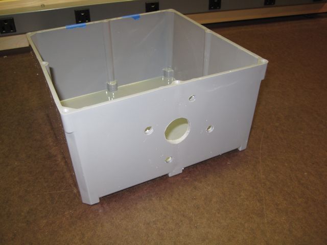
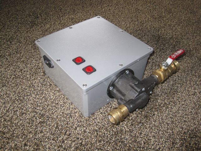
1. First, obtain a plastic box. I found that a Carlon 8" x 8" electrical box works well. Here is the box with a few holes for the motor and the pump housing. The pump housing will be reattached to the motor, sandwiching the box between the two.
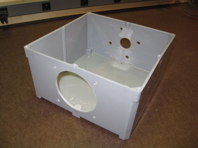
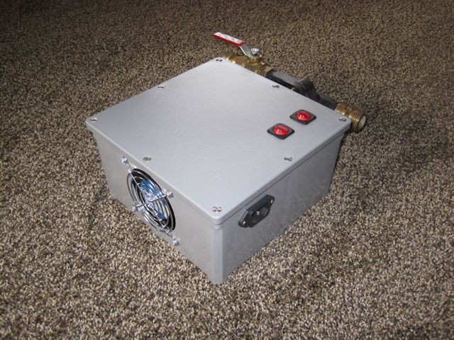
2. Opposite the holes for the motor, cut 4 holes for the fan and grille mount, and then a large hole for the exhaust. A hole saw or circle cutter works well for the larger hole. Not shown, but be sure to drill about 8-12 holes under the motor so that when the fan runs, it draws air across the motor and out the back.
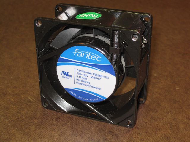
3. The fan you choose should be a 110 volt AC fan. Here is the one I used, bought from FrozenCPU:
4. For power, I found that a PC power supply plug works well. You'll probably have to clean solder off the back connectors. Here are a couple views of the front and back of the plug:
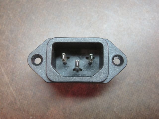
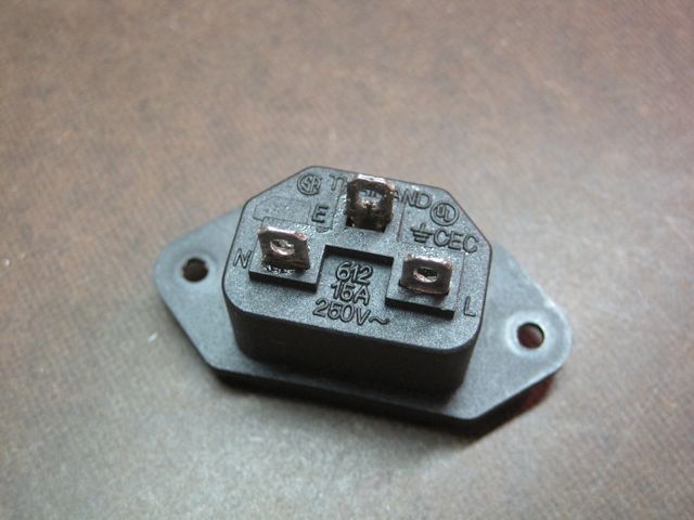
Note the letters to help you connect the correct wiring inside the box:
L = Line (black)
N = Neutral (white)
E = Earth/ground (green)
4. The switch can be a simple on/off, but I chose a lighted one. Here is what the connectors look like on the back of the switch:
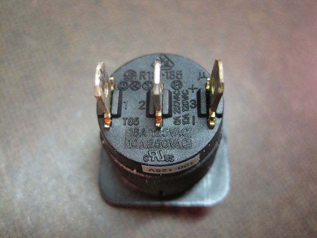
1 = Line (black)
2 = Load, also called switched line (also black)
3 = Neutral (white)
5. Here is a wiring diagram for lighted switches:
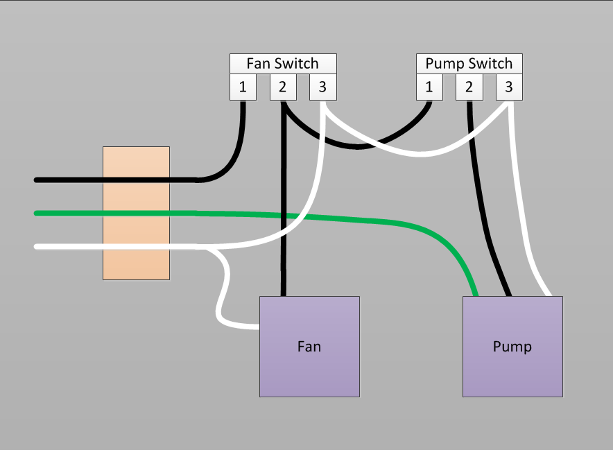
A little explanation:
- Power goes to fan switch connector #1.
- Fan switch connector #2 sees power when the fan is switched on, and sends power to the fan and also the motor switch.
- The pump switch connector #1 only sees power when the fan switch is on. When this occurs, and then the pump switch is closed, it send power out pump switch connector #2 to the pump.
- All neutrals are tied.
- Only the pump needs the ground, direct from the PC power plug.
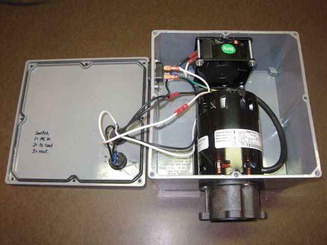
6. Wiring complete:
7. Final product:
A couple notes:
- When you test, be sure to remove the pump impeller housing. This is so that you don't run the impeller dry. You can reattach it once you know everything works, and plan on having fluid in the housing.
- Always use a GFCI outlet when testing or operating the pump.
- Do not attempt this if you are not comfortable around electricity.
- Keep hand clear of electrical parts when you have the lid removed and you have the power hooked up.
- Be sure to follow your pump's recommended lubrication schedule. This will require removal of the lid and oiling through the galleys on the motor.
- Install a couple small rubber feet on the underside so that the vent holes can get plenty of air.